Matek ExpressLRS Receivers and CRSF to PWM boards
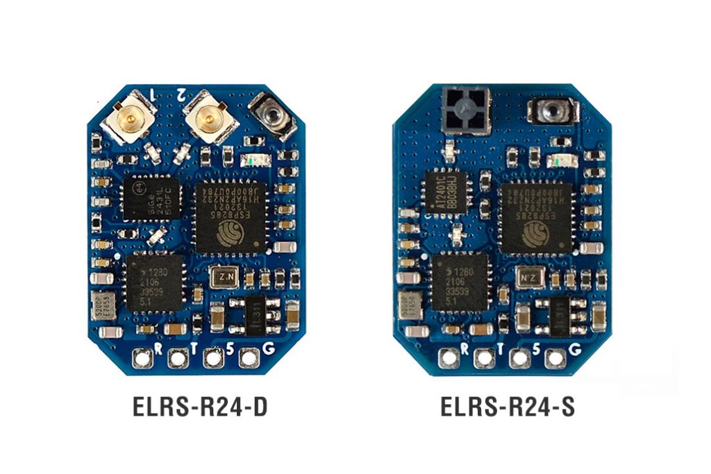
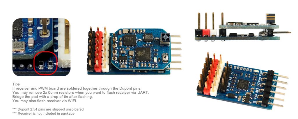
Matek (Matek Systems or MatekSys) stepped into ExpressLRS train. Matek released two ExpressLRS receivers – ELRS-R24-D and ELRS-R24-S. Matek has a record of the reputable manufacturer, so the quality of their products should be high.
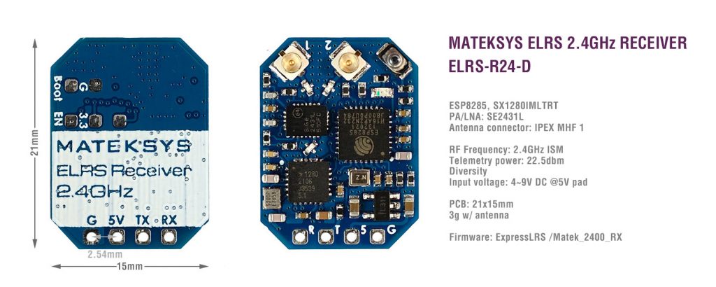
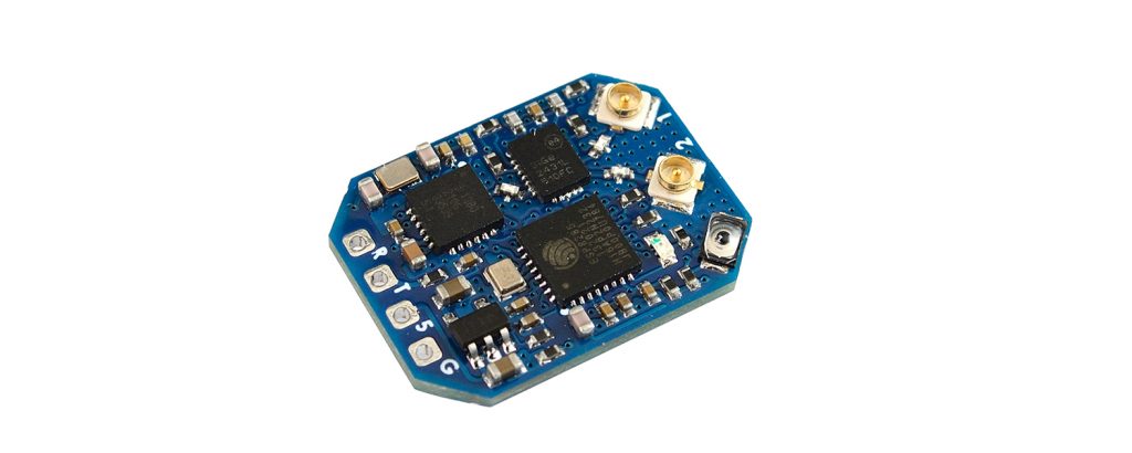
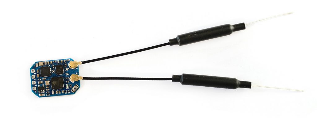
The first Matek ELRS-R24-D ExpressLRS receiver has diversity antennas (antenna switching diversity) and the most powerful PA/LNA on the ELRS receivers so far and is capable of outputting the 22.5dBm (~180mW) of the telemetry power. The weight of the receiver with two dipole antennas is 3 grams.
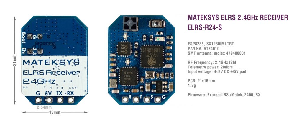
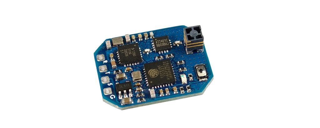
The second Matek ELRS-R24-S ExpressLRS receiver has SMD ceramic antenna
Release date: Mid October
Prices: ELRS-R24-S – MSRP $17.99 ELRS-R24-D – MSRP $19.99
ELRS-R24-D (diversity antenna) Specifications:
- ESP8285, SX1280IMLTRT
- PA/LNA: SE2431L
- Antenna connector: IPEX MHF 1
- RF Frequency: 2.4GHz ISM
- Telemetry power: 22.5dbm (177mW)
- Diversity: antenna-switching, default ANT2
- Receiver protocol: CRSF
- Input voltage: 4~9V DC @ 5V pad
- Power dissipation: 40~45mA(before binding), 70~75mA(binding), 90~95mA(wifi mode)
- PCB size: 21mm x 15mm
- Weight: 3g w/ 2x antennas
- Packing: 1x ELRS-R24-D, 2x IPEX MHF1 Antennas
Firmware
- ExpressLRS MATEK_2400_RX
- ELRS-R24-D: enable “USE_DIVERSITY” (checked) when flashing in ExpressLRS configurator
ELRS-R24-S https://www.banggood.com/MATEKSYS-ELRS-R24-S-2_4GHz-ExpressLRS-ELRS-Receiver-…-1900905.html
ELRS-R24-S (SMD antenna) Specifications:
- ESP8285, SX1280IMLTRT
- PA/LNA: AT2401C
- molex 479480001 SMT antenna
- RF Frequency: 2.4GHz ISM
- Telemetry power: 20dbm (100mW)
- Receiver protocol: CRSF
- Input voltage: 4~9V DC @ 5V pad
- Power dissipation: 40~45mA(before binding), 60~65mA(binding), 90~95mA(wifi mode)
- PCB size: 21mm x 15mm
- Weight: 1.2g
- Packing: 1x ELRS-R24-S
Firmware
- ExpressLRS MATEK_2400_RX
- ELRS-R24-S: disable “USE_DIVERSITY” (unchecked) when flashing in ExpressLRS configurator
Matek also released industry first CRSF to PWM (Crossfire to Servo) protocol converter adapter boards.
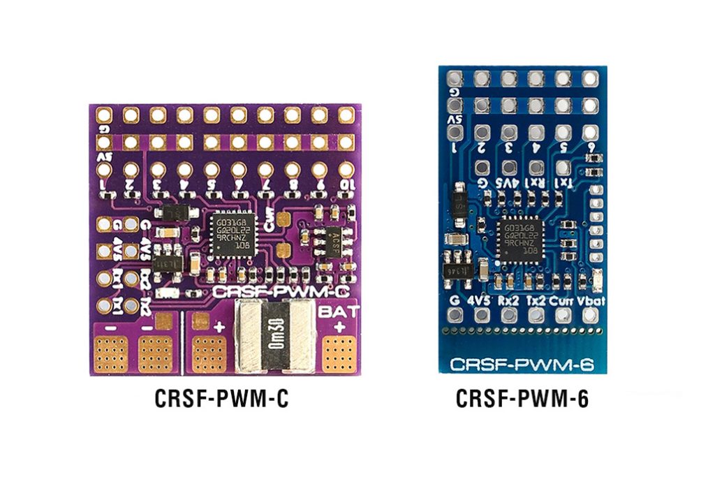
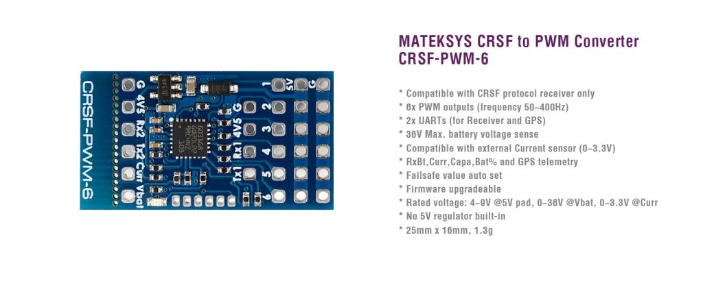
Matek CRSF-PWM-6 has 6 PWM servo outputs. Has integrated voltage sensor and external current sensor can be connected. PWM output frequency can be adjusted for faster servos (50Hz default, 100, 160, 330, 400Hz).
CRSF-PWM Converter, CRSF-PWM-6 specifications:
- Compatible with CRSF protocol receiver only
- 6x PWM outputs
- PWM frequency configurable (50Hz default, 100,160,330, 400Hz)
- 2x UARTs (for Receiver and GPS)
- Telemetry ID: RxBt, Curr, Capa, Bat%, GPS, GSpd, Hdg, Alt, Sats
- 36V Max. battery voltage sense (1K:10K voltage divider built-in)
- Compatible with external Current sensor (0~3.3V)
- Vbat and Current sensor scale configurable
- Failsafe value auto set
- Firmware upgradeable
- Rated voltage: 4~9V @5V pad, 0~36V @Vbat, 0~3.3V @Curr
- No 5V regulator built-in
- 25mm x 16mm, 1.3g
- Packing: 1x CRSF-PWM-6, Dupont 2.54 pins
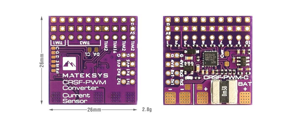
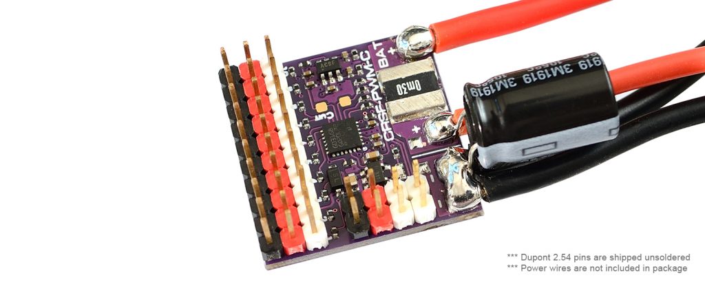
Matek CRSF-PWM-C converter board has 10 PWM servo outputs. Has built-in 90A continuous current sensor.
CRSF-PWM Converter, CRSF-PWM-C specifications:
- Compatible with CRSF protocol receiver only
- 10x PWM outputs
- PWM frequency configurable (50Hz default, 100,160,330, 400Hz)
- 2x UARTs (for Receiver and GPS)
- Telemetry ID: RxBt, Curr, Capa, Bat%, GPS, GSpd, Hdg, Alt, Sats
- 36V Max. battery voltage sense (1K:10K voltage divider built-in)
- Current sensor built-in (90A continuous /220A Peak), current scale = 150 by default
- Vbat and Current sensor scale configurable
- Failsafe value auto set
- Firmware upgradeable
- Rated voltage: 4~9V @5V pad, 0~36V @BAT+
- No 5V regulator built-in
- 26mm x 26mm, 2.8g
- Packing: 1x CRSF-PWM-C, 1x low ESR capacitor, Dupont 2.54 pins
Pinouts and Pads
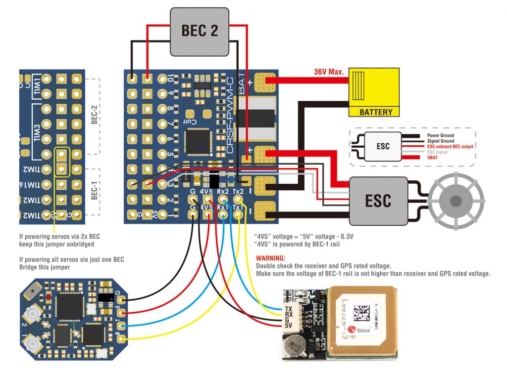
- Tx1/Rx1(UART1) for CRSF protocol Receiver
- Tx2/Rx2(UART2) for GPS/firmware update/setting parameters
- 1~10: CH1~CH10 PWM outputs
- Curr: current sensor signal (0~3.3V)
- Vbat: Battery voltage sensing (0~36V)
- G: ground
- 4v5 pad voltage = 5V pad voltage -0.3V, make sure the voltage on 5V pad is not higher than receiver and GPS rated voltage.
Failsafe
- Failsafe value is set automatically after CRSF-PWM board is powered on and receive CRSF signal. LED blinks 8 times quickly.
- Failsafe value = The PWM value of each channel(except CH3) when CRSF signal is received by CRSF-PWM board for the first time
- CH3 is specially arranged for the throttle, Failsafe value = 988 by default.
- Usually put the Throttle joystick to the lowest point, put AIL(Roll), ELE(Pitch), RUD(Yaw) middle before powering on receiver.
LED status
- slow blinks: CRSF-PWM board doesn’t receive CRSF signal, e.g., receiver is not bound with transmitter, receiver is not connected to UART1 of CRSF-PWM board.
- 8x quick blinks: CRSF-PWM board received CRSF signal and failsafe value is saved.
- solid ON: CRSF-PWM board and receiver are working normally
- 2x slow blinks between 8x fast blink and solid on: CLI mode is active
GPS telemetry
- Compatible with GPS NMEA protocol
- GPS “TX” to CRSF-PWM board “RX” Single wire half duplex UART connection, CRSF-PWM board “TX” to GPS “RX” is not essential.
- Support GPS Telemetry ID: GPS, GSpd, Hdg, Alt, Sats
- u-blox series GPS can output “0+1 – UBX+NMEA” protocol by default
- Sensors(GPS, GSpd, Hdg, Alt, Sats) will blink in Transmitter TELEMETRY tab once CRSF-PWM board has connection with GPS.
- Troubleshooting for no GPS telemetry, double check the wiring between GPS and CRSF-PWM board, some u-blox GPS may don’t output NMEA protcol, you need to be reverted GPS to default configuration in u-center.
TIM & PWM Frequency
- PWM frequency on all 10x Channels can be configured according to TIM
- PWM run at 50Hz by default
- TIM2: CH1, CH2, CH4
- TIM16: CH3
- TIM3: CH5, CH6, CH7, CH8
- TIM1: CH9, CH10
CLI mode
- If CRSF-PWM board doesn’t detect GPS connected to UART2 within 10 seconds after powering on, CLI mode will active.
- After CLI mode is active, CRSF-PWM board can be connected to configurator via USB-TTL module/FC passthrough.
- in CLI mode, CRSF-PWM board firmware can be updated
- CLI mode has no effect to receiver CRSF signal and PWM outputs
Matek CRSF to PWM converter CRSF-PWM-C connection diagram:


do these support sensors?
can i use my normal crossfire rx, connect a pwm current sensor or altimeter to the adapter and still recieve that info on my transmitter?
As long as I understand (still missing the full detailed information) the MCU on the converter board is capable of measuring the CURRent, VBat also reads the data from GPS module and sends this data to the ExpressLRS (or any other CRSF compatible?) receiver. So you don’t need the FC to get all this and sent via CRSF telemetry.
I guess the PWM current sensor and altimeter is not supported.
that’s a bummer
but they would supported on the official tbs pwm apapter?
it’s only 6ch
TBS PWM adapter is just a breakout board, extends the 6CH pads from CRSF Nano receiver to the servo pins. Nothing more.
I don’t know whether it’s just me or if everyone else encountering issues with your blog.
It appears like some of the written text in your content are running off the screen. Can someone else please comment and let me know if this is happening to them as well?
This could be a issue with my browser because I’ve had this
happen previously. Thanks
Hello, thank you for your feedback. I’ve tested http://www.multirotorguide.com on the Chrome and Edge web browsers. Seems to work pretty good. The WordPress theme I’m using has responsive design and works on desktop and mobile devices.
I’ve written PM to your email address with some further questions if you don’t mind.
Edit: Either this comment is just a spam or the provided email is not correct – the e-mail didn’t reached the recipient.
Edit of edit: Yep, it turns out I’ve been talking to the spam machine, just a waste of my time. I hate these fake comments.